Replacing the Capacitor on a Seiko 3M22
Back in 1996, I picked up a Seiko Kinetic while on a cruise. At the time, I really liked the style and high hopes for it. It was the first watch in over 20 years of buying them that was remotely like an automatic. It certainly was not cheap!
For
the first year of ownership, I was alternately amazed and disappointed. It kept good time and I really enjoyed
playing with the Kinetic power display button. As well, I really liked the styling. On the other hand, the light gold plating on the bracelet came off real
fast, leaving a kind of burnished bronze/gold tone. To make matters worse, the gold plating on the case stayed on,
giving the watch an odd two-tone look.
But what was really disappointing was that as time went on, it held less
and less of a full charge.
After
a little over two years of ownership, I gave up on it as junk. Seiko wanted me to pay them to look at it
and I really decided that the technology was not worth a second look. I placed it in a drawer until about 2002,
when it came out as a test device for a watch winder I was building. At that point, it wouldn’t keep a charge for
over an hour to an hour and a half.
I
forgot all about it until a friend of mine asked me to look at his dead
Seiko. It was not a Kinetic, but just
thinking about it spurred me to Google the Internet. Lo and behold, I found that you could now replace the capacitor
with a battery! So for $9. 75 plus
shipping and handling, I ordered one.
And this begins the real story.
The Battery
Starting
in 2001, you were not able to buy the old capacitor (3029 011). If you ordered it, Seiko provided you with a
new part (3027 29N), which in fact, is a rechargeable battery. Seiko mentions that you need to have a new
battery clamp, and in fact, provides it with the rechargeable battery.
Why would they do that? I looked at the drawings they provided and decided that the rechargeable battery must be thinner. With that guess, I ordered the part from www.SwatchBattery.com
Upon
receiving the part, my guess was verified. Indeed, the battery was thinner than the capacitor. Included in the packet was the new battery
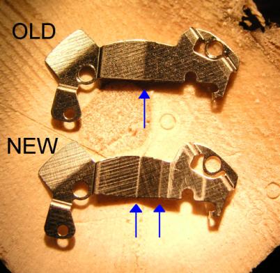
clamp. Below is a picture of the old
battery and the new battery. The yellow
arrow shows a notch on the soldered bridge (as if the thinner battery itself
was not a good enough indicator!).
The brackets are shown below. It is difficult to show the differences in the brackets, so I have highlighted the bends.
Watch Disassembly
I
should advise you that you should not attempt this unless you are familiar with
working on watches. While less complex
than a mechanical watch, quartz watches are pieced together in an almost
impossible origami patchwork style. At
any rate, I will not be held accountable for your actions!
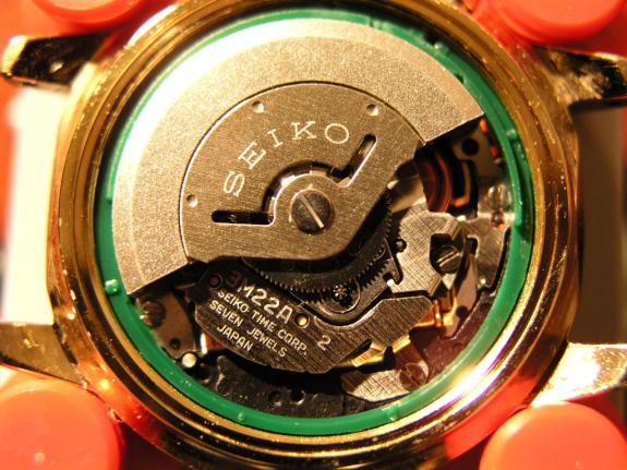
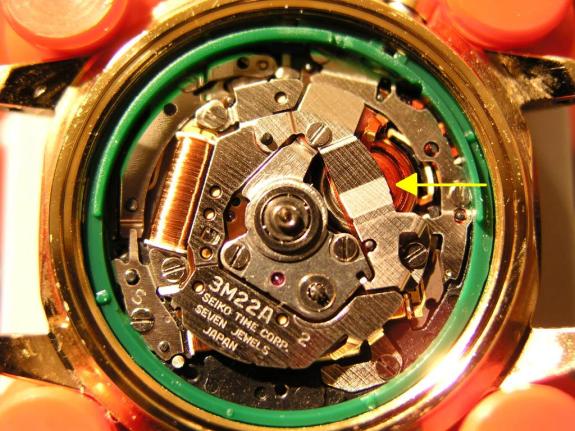
Here
is a picture of the movement once the cover is wrenched off:
Using tweezers or a toothpick, prevent the rotor from turning while you remove the screw. After removing the screw that holds the rotor on, the movement will look like this:
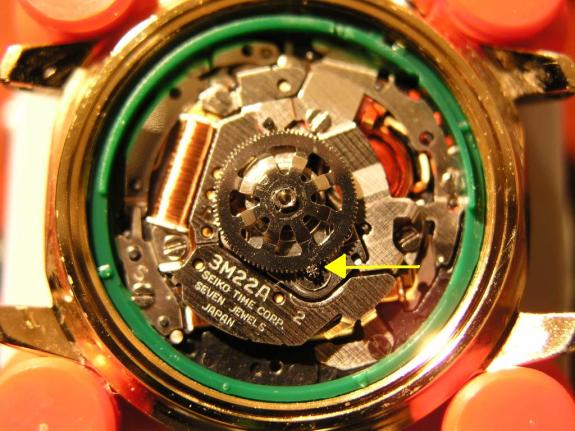
The
yellow arrow above shows the engagement of the rotor gear with the inner
winding assembly. This is a good thing
to remember during assembly. While it
is hard to tell from this angle, the rotor gear is actually inverted. Be sure to install it in the same
fashion. Using tweezers, gently remove
the rotor gear and place it with the rotor and its screw. At this point, the movement will look like
this:
Now,
it is time to remove the battery holder. And yes, in case you are wondering, that is the new battery holder. I did not have the sense or the time to take
the pictures from disassembly to reassembly, but this should be helpful
nevertheless. Remove the two screws
holding the battery holder in place.
Keep in mind that screws in quartz watches are much shorter than those
of their mechanical counterparts, so be ready to catch them and remove them
from the movement.
After
removing the two screws and the battery holder, you will notice the piece of
Mylar covering the old battery. It
should look something like this:
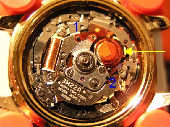
The1 and 2 you see in the
picture are two pins. You must fit the
Mylar back on these pins when reassembling the movement. Remove the Mylar and your watch will look like
this:
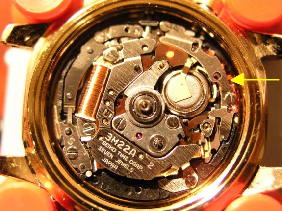
The
next piece to remove is the holder that keeps the battery/capacitor assembly in
place. This is designated by the yellow
arrow. Remove the two screws holding it
in place and place it and the two screws in the same safe place as the rest of
the parts. Your movement will now look
like this:
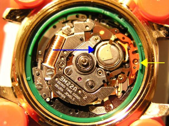
The
blue arrow points to the battery/capacitor assembly while the yellow arrow
points to the Mylar covering part of the assembly. Remove both pieces and make sure not to loose the Mylar! Also note its position and how it lines up
with a screw hold and a pin. This is
necessary to line up everything during the final assembly.
After
removing these parts, your movement will look like this:
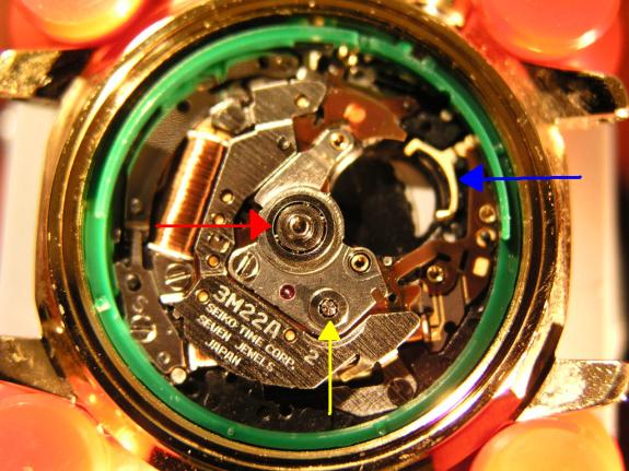
Just
to keep our bearings, the red arrow is the hub for the rotor, the yellow arrow
is part of the inner winding assembly, and the blue arrow shows the battery
contact at the bottom of the movement. You may also note that a screw is missing just below and to the right of
the rotor hub. I had done some
additional work like cleaning and lubricating. That is beyond the scope of this project. Suffice to say, you should not remove that screw. J
Watch Reassembly
Just
reverse the steps! Make sure you don’t
drop any parts or introduce any more dust than necessary into the
movement. Also, be sure not to over
tighten any of the screws. If you strip
one or break one, there is not much that can be done without owning some
specialized tools.
It’s Done, Now What?
First
thing you will want to do is charge the watch. A full charge would be nice, but it would take forever. Try to make at least 1,700 to 2,000 swings
from side-to-side to charge the watch. This should help you establish some baseline performance for it. The rechargeable battery seems to be capable
of quite a bit, but unless you run a jackhammer, you may never realize it. Below is a table from summarized from some
Seiko information that should be helpful.
|
|
Indicator |
Power Reserve |
Swings Needed |
|
Old
Capacitor
|
5 seconds
|
3 hours
|
100 times
|
|
10
|
1 day
|
500
|
|
|
20
|
2 days
|
800
|
|
|
30
|
3 days
|
1,200
|
|
|
New
Battery
|
5
|
3 – 10 hours
|
100
|
|
10
|
10 hours – 1 day
|
200
|
|
|
20
|
1 – 40 days
|
700
|
|
|
30
|
40 days
|
16,000 |
As
you can see, the rechargeable battery is supposed to have a lot going for
it. Assuming, that is, you can ever get
it fully wound up!
© Daniel N. Ravenna 2003